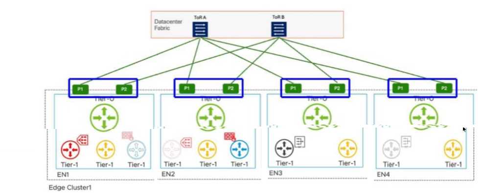
P1 and P2 interfaces on EN2
In a VMware Cloud Foundation (VCF) environment, the interaction between different tiers of logical
gateways is governed by the placement of Service Routers (SR). When a Tier-1 Gateway is configured
with stateful services, such as a Gateway Firewall (GFW), it must operate in Active/Standby (A/S)
mode. This ensures that session state is maintained on a single active node at any given time.
According to the provided diagram and VCF architectural guidelines, the Active Tier-1 SR is hosted on
Edge Node 2 (EN2). In a multi-tier NSX design, the Tier-1 gateway is logically connected to the Tier-0
gateway via an internal transit segment (often referred to as the Router Link). While the Tier-0
gateway itself is running in Active/Active (A/A) mode across all nodes (EN1 through EN4) to provide
high-bandwidth ECMP to the physical Top-of-Rack (ToR) switches, the Tier-1's path to the external
world is constrained by its own current location.
Traffic originating from a workload segment attached to this Tier-1 will be processed by the GFW on
EN2. From there, the packet must exit to the physical network via the Tier-0 uplinks. Because the
Tier-1 SR is localized to EN2, it will utilize the local Tier-0 instances and their corresponding physical
uplinks located on that same node to avoid unnecessary inter-edge "East-West" hair-pinning over the
Geneve overlay.
The highlighted options P1 and P2 on EN2 represent the specific physical/logical uplink paths (VLAN-
backed) that the Tier-1 GFW on EN2 will use to reach ToR A and ToR B. Even though EN1, EN3, and
EN4 also have active Tier-0 paths, the stateful nature of the Tier-1 on EN2 means its North-South
traffic flow is anchored to the uplinks of its current host node. Therefore, to identify the ECMP paths
actively utilized by that specific stateful Tier-1 service, the administrator must look at the uplink
interfaces (P1/P2) associated with the node where that Tier-1 is active.