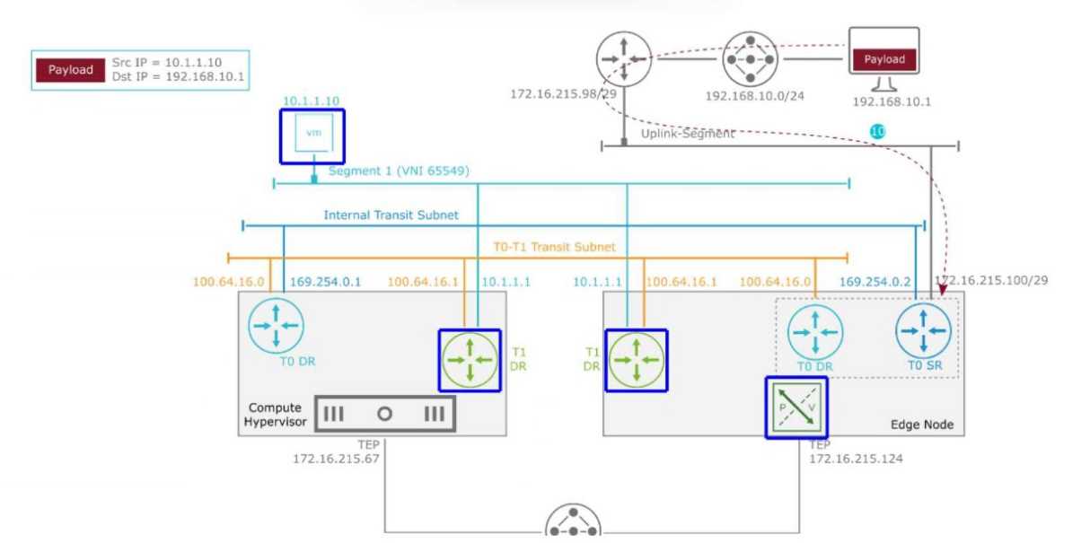
the administrator should click the Tier-1 DR icon located within the Edge Node.
Comprehensive and Detailed 250 to 350 words of Explanation From VMware Cloud Foundation (VCF)
documents: In a VMware Cloud Foundation (VCF) environment, North-South traffic flows through a
hierarchical routing structure composed of Tier-0 and Tier-1 Gateways. Each gateway is further
divided into a Distributed Router (DR) component, which runs as a kernel module on all Transport
Nodes (ESXi and Edges), and a Service Router (SR), which provides centralized services and resides on
the Edge Nodes.
According to the packet walk logic for an incoming (North-to-South) packet, once the traffic arrives
from the physical router at the Tier-0 Service Router (SR) on the Edge Node, it must be routed toward
the destination virtual machine (10.1.1.10). In a multi-tier NSX architecture, the Tier-0 SR identifies
that the destination subnet belongs to a connected Tier-1 Gateway. The communication between the
Tier-0 and Tier-1 gateways occurs over an internal transit subnet, often referred to as the Router Link
(in this diagram, represented by the 100.64.16.0/31 subnet).
The "Next Hop" for the packet currently residing at the Tier-0 SR on the Edge Node is the Tier-1
Distributed Router (DR) instance located on that same Edge Node. This is because the Edge Node
participates as a Transport Node in the overlay and maintains local instances of all Distributed
Routers to ensure efficient path processing. After the packet is processed by the local Tier-1 DR on
the Edge Node, it determines that the destination VM is residing on a remote host (Compute
Hypervisor). Only then is the packet encapsulated in a Geneve header and sent via the Tunnel
Endpoints (TEP) from the Edge Node (172.16.215.124) to the Compute Hypervisor (172.16.215.67).
Therefore, the Tier-1 DR on the Edge Node is the immediate logical next step in the routing pipeline
before any host-to-host encapsulation occurs.