
Q: 10
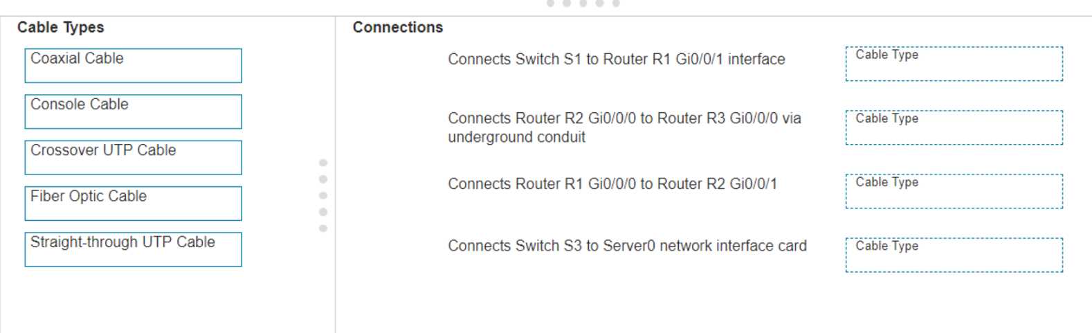
DRAG DROP Examine the connections shown in the following image. Move the cable types on the right to the appropriate connection description on the left. You may use each cable type more than once or not at all. 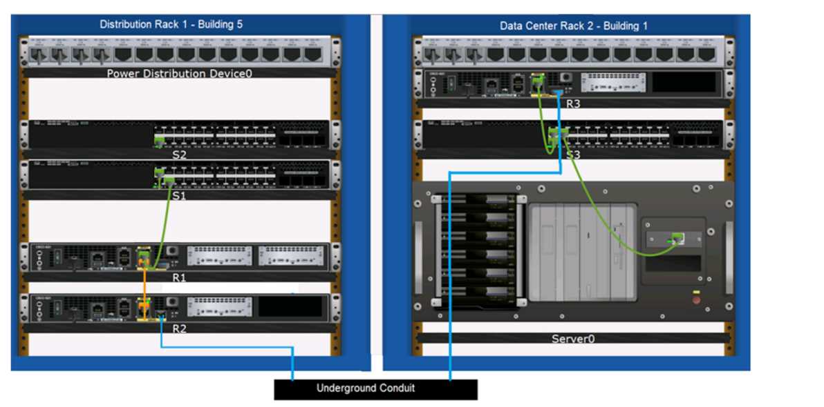
Drag & Drop
Discussion
Pretty textbook cabling for these types of connections. Switch to router and switch to server both use straight-through UTP, routers underground get fiber, and router-to-router is crossover. Can't see another way unless they're hiding a trick.
S1 to R1: Straight-through, R2 to R3 (underground): Fiber Optic, R1 to R2: Crossover, S3 to Server0: Straight-through. These follow Cisco standard wiring rules-straight-through for switch-to-router/server, crossover for router-to-router. Pretty sure that's it but let me know if you spot something off.
S1 to R1: Straight-through, R2 to R3 via conduit: Fiber, R1 to R2: Crossover, S3 to Server0: Straight-through. Usually folks mix up crossover and straight-through here.
S1 to R1: Straight-through, R2 to R3 underground: Fiber optic, R1 to R2: Crossover, S3 to Server0: Straight-through. Pretty sure that's how Cisco standard cabling looks here but if I'm missing a gotcha let me know.
Yeah, usual Cisco rules: straight-through for switch-router and switch-server, fiber for underground, crossover for router-router.
Makes sense to use Straight-through for Switch S1 to Router R1 and S3 to Server0, Fiber Optic for underground between R2 and R3, and Crossover for router-to-router (R1 to R2). That matches Cisco cabling standards, pretty confident here.
Switch S1 to Router R1: Straight-through UTP, R2 to R3 (underground): Fiber Optic, R1 to R2: Crossover UTP, S3 to Server0: Straight-through UTP. That's standard cabling logic for these setups, I think-unless they're hinting at something tricky. Agree?
Connects Switch S1 to Router R1: Straight-through UTP, R2 to R3 via underground: Fiber Optic, R1 to R2: Crossover UTP, Switch S3 to Server0: Straight-through UTP. This matches standard cabling practice, pretty sure this is right. Anyone else seeing different pairings?
S1-R1: Straight-through, R2-R3 underground: Fiber optic, R1-R2: Crossover, S3-Server0: Straight-through. Console cable's a common trap but not for data paths here.
Switch S1 to Router R1 = Straight-through UTP, Router R2 to R3 via underground = Fiber Optic, Router R1 to R2 = Crossover UTP, Switch S3 to Server0 = Straight-through UTP. That's the usual setup for these devices, but if anyone thinks there's a twist here let me know. Not 100% if they're trying to trip us up with device types.
Be respectful. No spam.
